So I built my first keyboard.
With so many options, I wanted something for my first build that was relatively available and accessible, so I landed on the KPrepublic XD87. Thankfully louwii has a wonderful build log documenting his build, which I used for the majority of my experience, however, I had a few items that tripped me up which may be useful for folks building this kit in the future.
Kit contents
I’ve heard that there are some advantages of purchasing from AliExpress rather than from the KPrepublic store, so that’s what I did. I did hear that the plate was back ordered and that it would take 1-2 weeks to restock, but six days later I received a shipment notice and 26 days after the original order I had boxes in hand.
Here’s exactly what I ordered:
- XD87 Kit7
- Plastic Case – White
- Gateron Switches – Brown 3pin
- 2pin LEDs – White
- Type C Coiled Cable – White
- Domikey SA Classic Dolch Keycaps – SA CD AllinOne
- Everglide Transparent Gold Plated Stabilizers – EG GH60 Plus x1 Set
I didn’t see how to specify the options for the kit when I placed the order, so I sent a chat message immediately after placing the order, and that seemed to work without incident. Also, don’t forget the stabilizers, as they’re not included and that’s strange.
Build Notes
The following will be more or less in the order that I encountered issues. Likely some of this was from lack of paying attention to louwii’s guide.
Soldering Iron
If you don’t have a soldering iron, the UY CHAN TS100 is fantastic. I had done a few smaller jobs with it, but for this assembly it was great.
RGB LEDs
My PCB came with the underglow RGB LEDs pre-soldered, which was helpful, but the reality is that the underglow effect is mostly non-existent with the current case design. I’m not young enough to be sold on all the RGB, so not a big deal for me.
Firmware
Firmware did not appear to be loaded out of the box, so I loaded something to at least make sure the LEDs were working.
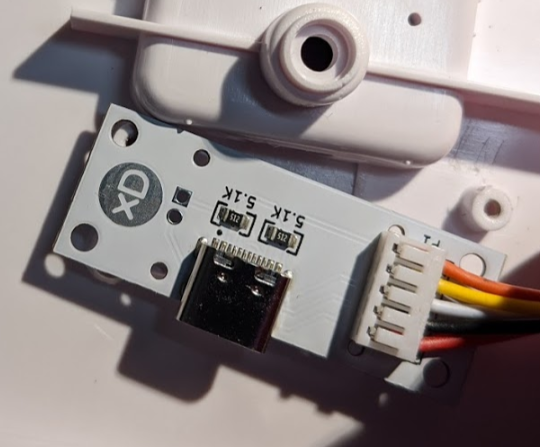
USB Module
The kit came with a Type-C module pre-installed on the back case. I ended up unscrewing it so I could leave it attached to the PCB while I soldered everything.
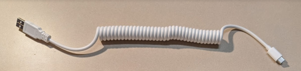
USB Type-C Cable
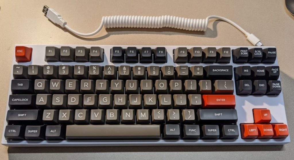
The included USB Type-C cable is only a little over 15 inches long, which for my needs is less than practical. I’m going to be trying my hand at a sleeved and coiled cable in a few weeks.
Initial Assembly Mistakes
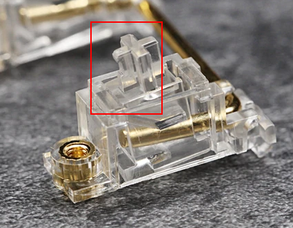
Pay attention to the orientation of the stabilizers. I attempted to install them the wrong way around, and almost broke one of the stabs. If you’re pushing too hard (which I was) they’re likely the wrong way. Also, I didn’t see notes on the orientation of the stem so I had to sort that out by looking at the photos on AliExpress. The notched side should point towards the screw hole.
Put the plate on BEFORE putting the switches in. I had built a Macro Pad from 1up Keyboards before that used PCB mounted switches, so I started right in mounting the switches for this build on the PCB and soldered a couple in place while wondering why it was sloppy. Don’t do what I did.
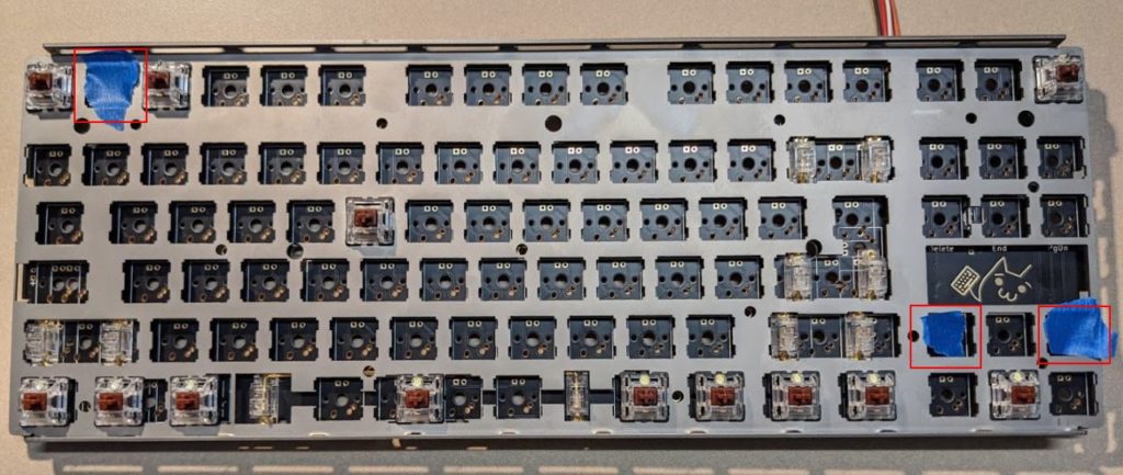
DON’T INSTALL A SWITCH NEXT TO THE ESC KEY. I did this twice, once before I put the plate on, and once again after. This was stated in louwii’s guide, but it’s easy to miss. I ended up putting tape over this spot and the other two locations to help me out because I’m an idiot.
Get a tool to remove switches, or pay attention to how they release from the plate. I didn’t have a tool and used pliers before I realized that the little tabs on the top and the bottom are what release things, almost breaking a few of the switches in the process. A small flathead screwdriver was what I used later on. An appropriate tool would have been better.
Backlight LEDs
I didn’t do the SIP socket route, so I soldered LEDs through the hole in the switch. Make sure that the longer leg of the LED (positive/anode) lines up to the square pad on each point, which typically is on the left if you’re looking at the front of the board, however, there are a few important exceptions which I’ll get to below.
As I installed these, I would insert the LEDs and bend the pins outward slightly to prevent them from falling out when I flipped the PCB over. Flip the board over, check and make sure the square pad has the longer leg, and then pin the LEDs in place with a little bit of solder on that square pad side.
Next I’d go back through with one hand on the LED (on the underside of the board now that it’s flipped over) and reheat that same pad with the iron in my right hand while pressing gently on the LED into the board with my left hand. This would reheat and align the LED snug up against the switch.
Finally, solder the cathode/negative side of the LED and add solder if necessary to the anode/positive leg. Repeat for the section of LEDs and test.
Bottom Row and Caps Lock Switch Placement
The supported layout info on the XD87 page was confusing to me, and I didn’t realize what the layout of a standard bottom was (1.25x for all modifiers, 6.25x for the spacebar). All I knew is that I wanted to get the board built quickly and use the keycaps I purchased.
There are a variety of mounting options on the bottom row, and I had originally tried centering them, but then testing keycap fitting I couldn’t get things to line up.
In short, what I determined was that for the bottom row, the modifier keys should be mounted towards the outside edges. So to the left of the spacebar, mount the switches on the leftmost point, and on the right side, use the rightmost point. This should allow the standard bottom row to fit, but test this out before soldering your switches in place.
This also means that the LEDs for the modifier switches to the right of the keyboard have the long leg (positive/anode) going the other way.
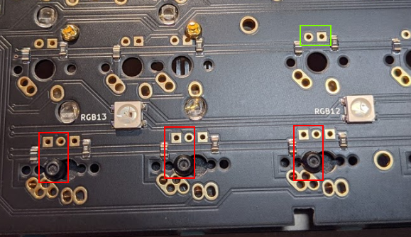
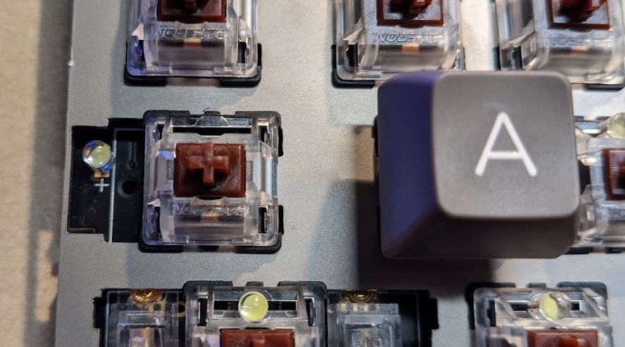
For the Caps Lock switch, the switch should be mounted on the right, closer to the A key, if you want to use the keycap that comes with the standard set of modifiers. There’s another version of the keycap that has this cool bump on it but I realized too late that the mount is in a different place, so oh well.
Also install the optional LED for Caps Lock light if desired.
Test Test Test
Test both the switches and the LEDs regularly. Aqua’S KeyTest seemed to work well enough for me for checking the switches, but testing the backlighting LEDs regularly is a good idea. I started by testing every four switches or so but eventually ended up doing rows or half rows as I got further into it.
Post-Build Thoughts
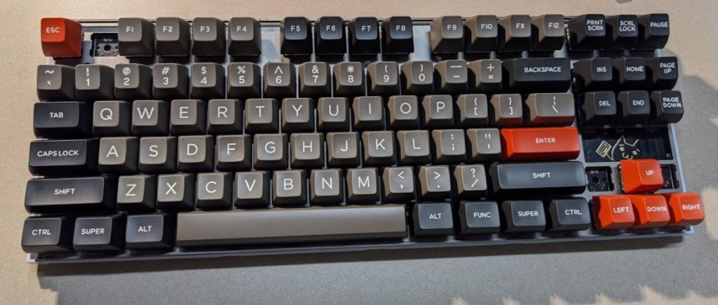
After getting through the initial set of mistakes (of which there were plenty), the rest of the assembly was pretty straightforward. Overall assembly was likely under 4 hours. I need to work through some of the firmware programming, but I typed this post on the keyboard and it’s been an enjoyable experience.
I don’t have much experience in the mechanical keyboard world, but compared to my currently daily driver (WASD CODE V2) here’s what I think:
- I still like browns. I have them on the CODE (Cherry) and again on the XD87 (Gateron). Admittedly, I haven’t spent a lot of time with any of the other styles, but it feels good.
- The F and J reference bumps don’t exist on these keycaps, and that’s a little weird but really only seems to matter when I’m bringing my hands back to the keyboard. I try and drive from the keyboard as much as I can already, but it does feel a little strange. (Edit: a coworker pointed out that the F and J keys are sculpted a little differently, and after realizing that it’s not so bad, and I can feel it. Also, those bumps are called homing bars.)
- The spacebar is pretty noisy, especially compared to the CODE. I may try some o-rings on it and a few of the larger keys. I flipped it over too, so trying to join the cool kids to try that out.
- Key height (SA Profile) doesn’t seem to have an effect on my typing, and I like the look.
- I wish I had better information on the lighting effect options. It’s pretty unclear at the moment. I may try QMK as there appear to be some updates as of July 2020, so we’ll see. As mentioned before, the RGB underglow can barely be seen, and I feel like the only way that would be visible is with a different bottom case.
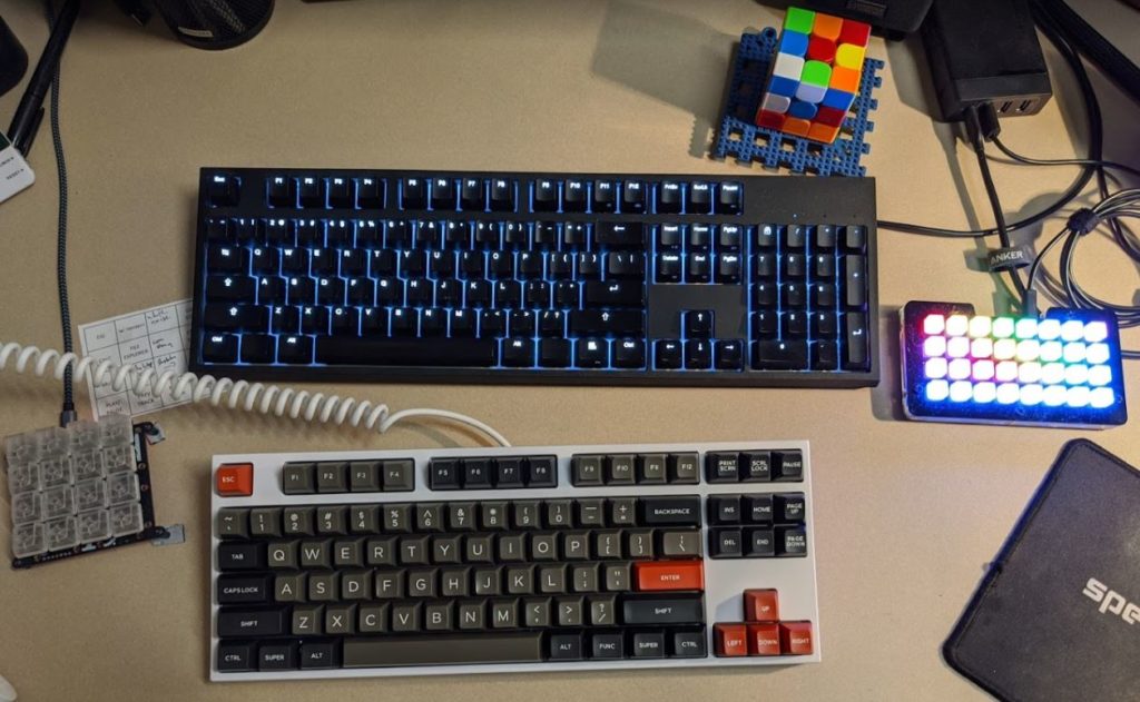
Highlighting the oh-so-short Type-C cable.
Big thanks again to louwii for his actual build log. Go read that for actual good info on assembling this keyboard. And thanks to KPrepublic for making a delivering a kit for me to build!